Armored, cooled sodium-air power unit for the Sodium-Operated Vehicle, Version 2. Concept-level estimates; not a validated engineering design.
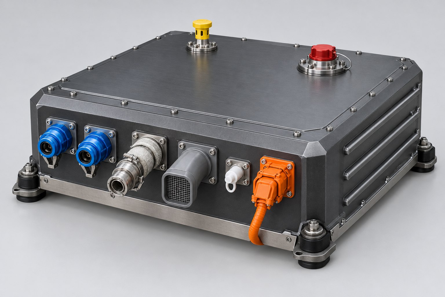
Figure 1. CCM exterior (artist rendering). Front-face ports, left to right: two coolant couplings, heat-traced sodium feed, air intake, catholyte drain, high-voltage connector. Top: burst-disc vent (yellow) and firefighting port (red).
1. Bottom Line
What it is. One sealed, armored box that replaces the steam reactor, hydrogen buffer, and PEM fuel cell from Revision 1. Sodium is oxidized directly in an electrochemical cell, so no hydrogen and no 350 °C reactor are involved.
Output. 30 kW continuous and 40 kW peak at the 400 V bus, from four independent 54-cell stacks. If one stack fails, the car keeps 75% of its power.
Efficiency. About 2.5 kWh of electricity per kg of sodium, versus 0.73 kWh in Revision 1. An 85 kWh trip needs about 34 kg of sodium instead of 116 kg. With today's sodium production, round-trip efficiency rises from about 7% to about 23%.
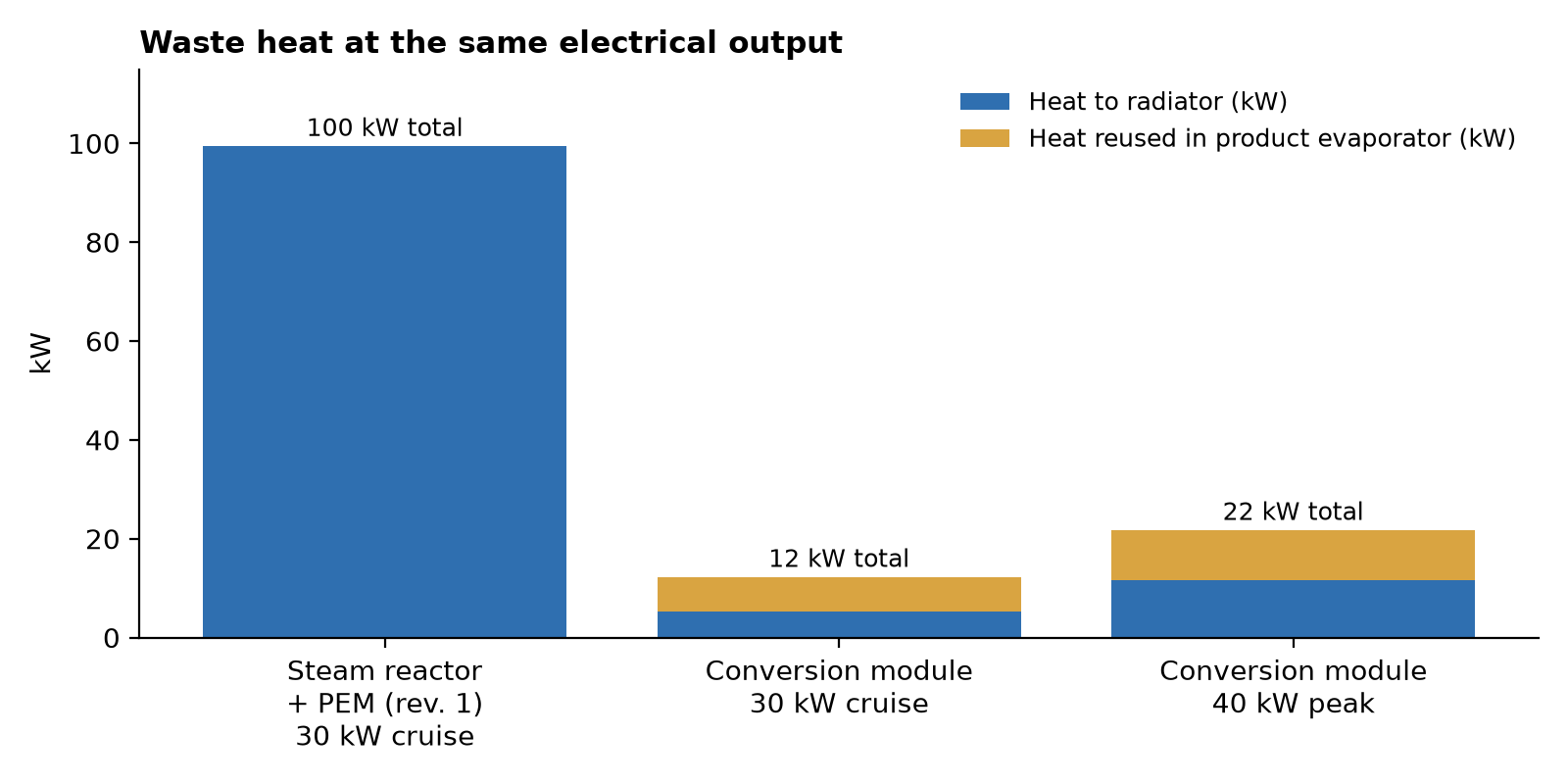
Heat. About 12 kW of waste heat at 30 kW cruise, versus about 100 kW for Revision 1. More than half of that heat is reused to dry the product, so the radiator only has to reject about 5 kW at cruise and 12 kW at peak.
Protection. The module has a multi-layer armored wall, a hermetic argon-filled liner, a cooled jacket that keeps the outer skin below 60 °C, under 3.5 kg of liquid sodium inside, and a crash sequence that separates sodium from water within 50 ms.
The main assumption. The module needs about 0.3 W/cm² of membrane power density. That is roughly 10 times the best published sodium-air lab cells, so treat it as a near-future or story-world technology.
2. Role in the Vehicle
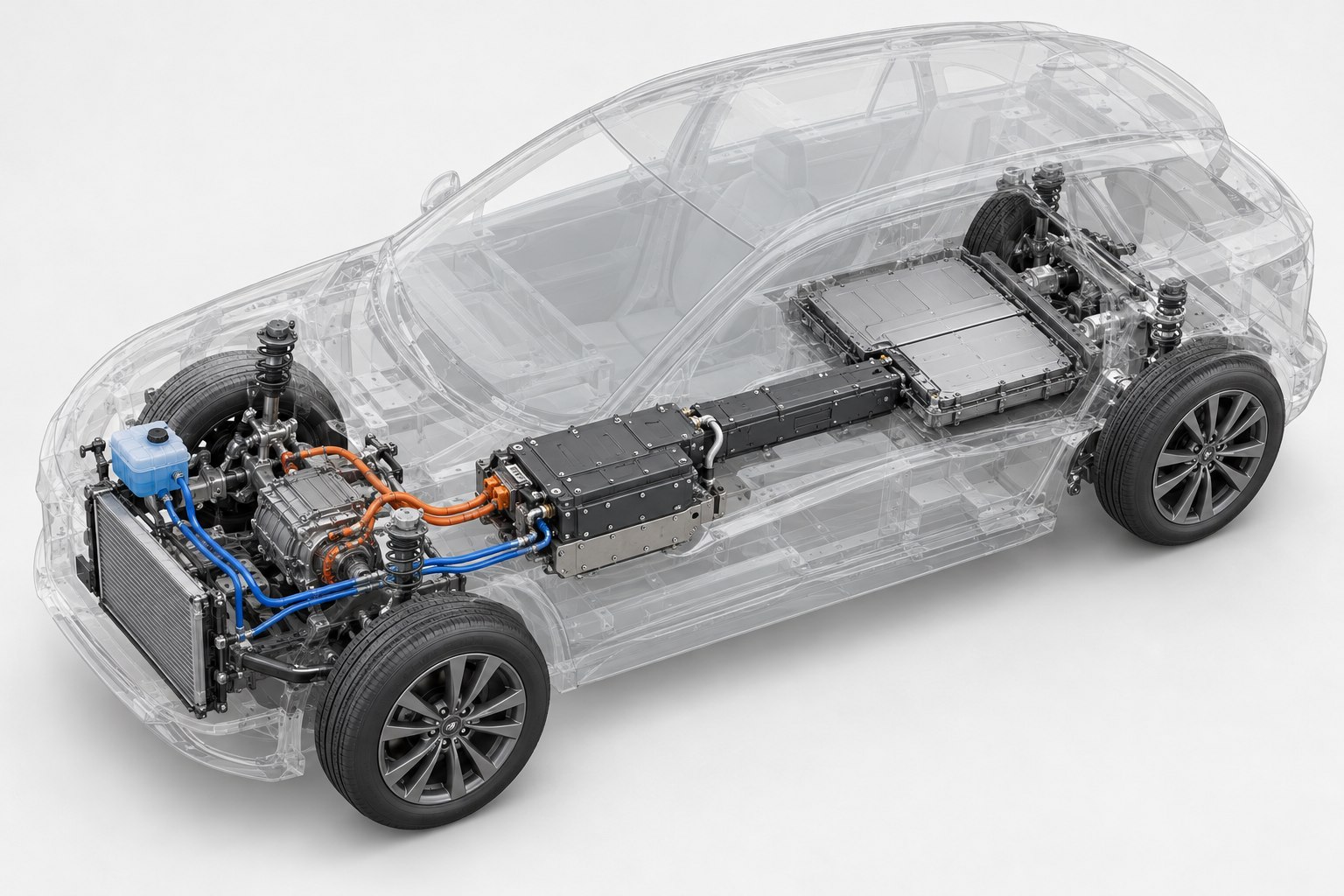
The CCM sits under the front-seat floor, centered between the side sills, immediately ahead of the sodium cassette in the center tunnel. It takes in liquid sodium from the cassette, filtered air, and make-up water from the front tank. It sends out DC power to the 400 V bus, warm coolant to the radiator and cabin heater, moist oxygen-depleted exhaust air, and a molten NaOH·H₂O product stream back to the spent side of the cassette.
Figure 2. Vehicle integration (artist rendering): CCM under the front-seat floor, cassette along the tunnel, water tank and radiator in front, and a 35 kWh battery under the rear seat.
3. Key Specifications
Parameter
Value
Continuous / peak net power
30 kW / 40 kW (60 s); larger peaks come from the 35 kWh battery
Cell chemistry
Liquid Na anode | NASICON ceramic membrane | 50 wt% NaOH catholyte | air cathode
Overall reaction
Na + ¼ O₂ + ½ H₂O → NaOH
Cells
216 planar cells, 500 cm² each, 10.8 m² total membrane area
Stacks
4 × 54 cells; ~130 V each at rated load, ~162 V open circuit
Operating point (rated)
2.4 V per cell, 125 mA/cm², 0.30 W/cm²
Operating temperature
110–120 °C (sodium molten above 98 °C)
Power electronics
One DC/DC boost converter per stack, 400 V output, each with a pyrotechnic disconnect
Sodium use at 30 kW
11.6 kg/h
Air flow at 30 kW
~10 g/s (~480 L/min), twice the oxygen the reaction needs
Liquid sodium inside module
< 3.5 kg (about 15 g per cell, held in a steel wick)
Each cell oxidizes sodium on one side of a NASICON ceramic membrane. Sodium ions cross the membrane and meet hydroxide formed at an air electrode in the aqueous catholyte:
From standard thermodynamic data, the overall reaction has ΔG ≈ −301 kJ/mol and ΔH ≈ −327 kJ/mol to dilute NaOH. That gives a theoretical open-circuit voltage of about 3.1 V. Real cells show about 2.9–3.0 V. For example, a seawater cell using dissolved oxygen discharged at about 2.9 V (OSTI, rechargeable seawater battery). This design assumes 2.4 V per cell at rated load.
Per kg of sodium
Revision 1 (steam + PEM)
CCM (Version 2)
Electricity at 400 V bus
0.73 kWh
2.51 kWh
Waste heat
2.42 kWh
0.98 kWh (0.54 kWh reused in evaporator)
Water consumed or bound in product
0.78 kg
1.17 kg (0.39 reaction + 0.78 hydrate)
Product
1.74 kg NaOH (solid)
2.52 kg NaOH·H₂O (melts ~65 °C)
Sodium for an 85 kWh trip
116 kg
34 kg
Round trip at 10 kWh/kg sodium production
~7%
~23%
Electricity per kg: 2.4 V × 96,485 C/mol × 43.5 mol/kg gives 2.80 kWh gross. After about 7.5% for blowers, pumps and heaters, and 3% for DC/DC conversion, about 2.51 kWh reaches the bus.
5. Internal Architecture
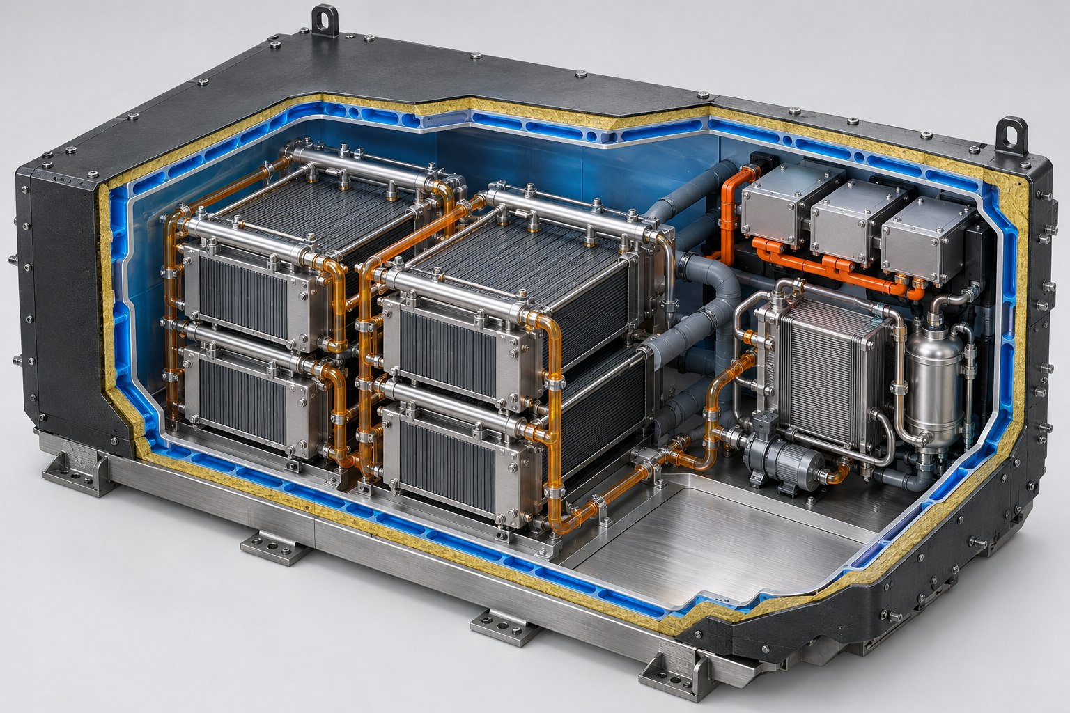
Figure 3. Cutaway (artist rendering). Wall layers from outside in: armor, aramid spall liner, coolant jacket, hermetic liner. Inside: four cell stacks in a 2 × 2 grid with sodium, catholyte and air manifolds, plus the balance-of-plant bay (heat exchanger, pump, evaporator, DC/DC converters). The rendering shows three converters; the design uses four, one per stack.
5.1 Cell Stacks
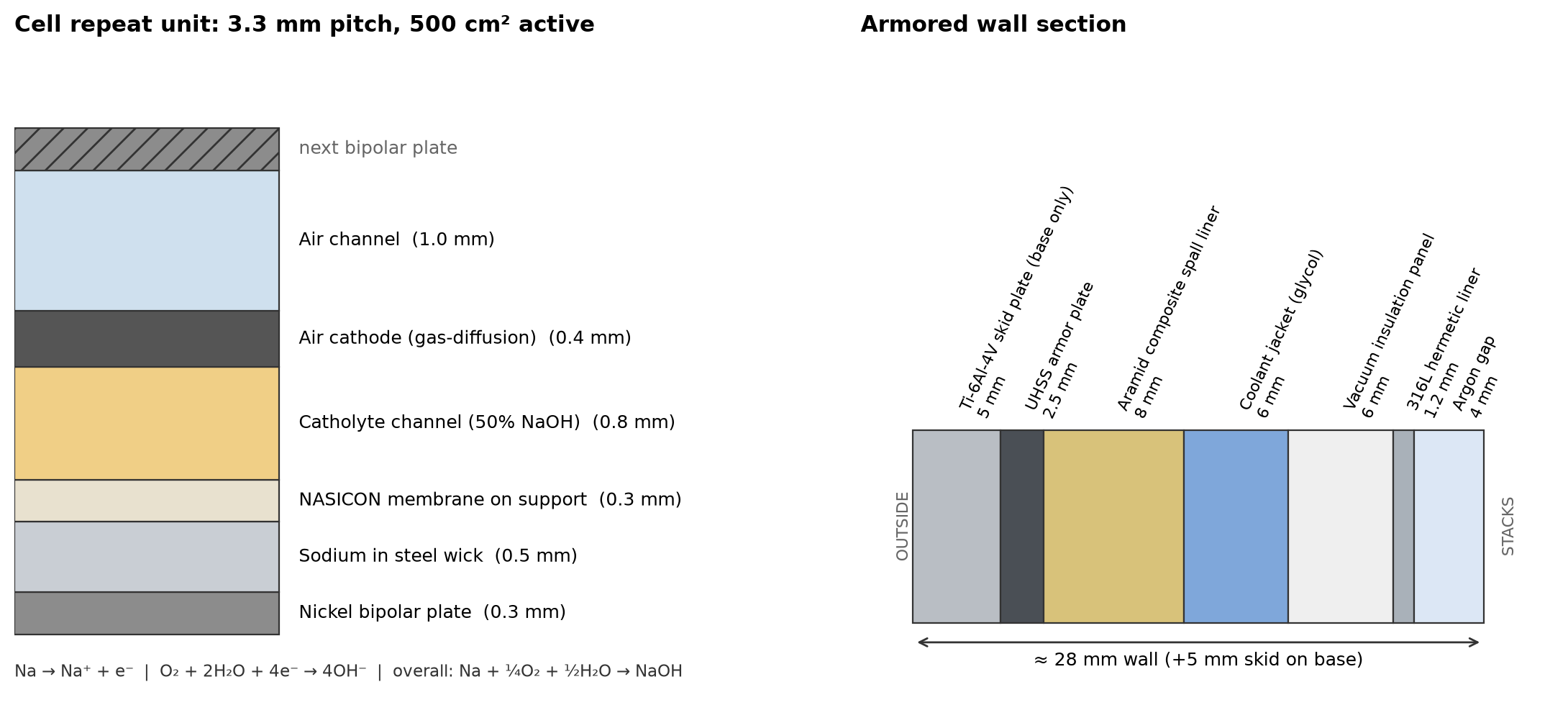
Each planar cell is a 3.3 mm repeat unit. Each stack has 54 cells between nickel end plates held by tie rods with spring-loaded compression, which allows for thermal growth. The four stacks are electrically and hydraulically independent. Each has its own sodium valve, catholyte valves and DC/DC converter, so a damaged stack can be isolated while the other three keep running.
Figure 4. Left: cell repeat unit (3.3 mm pitch, 500 cm² active). Right: armored wall section (layer thicknesses in mm).
5.2 Flows
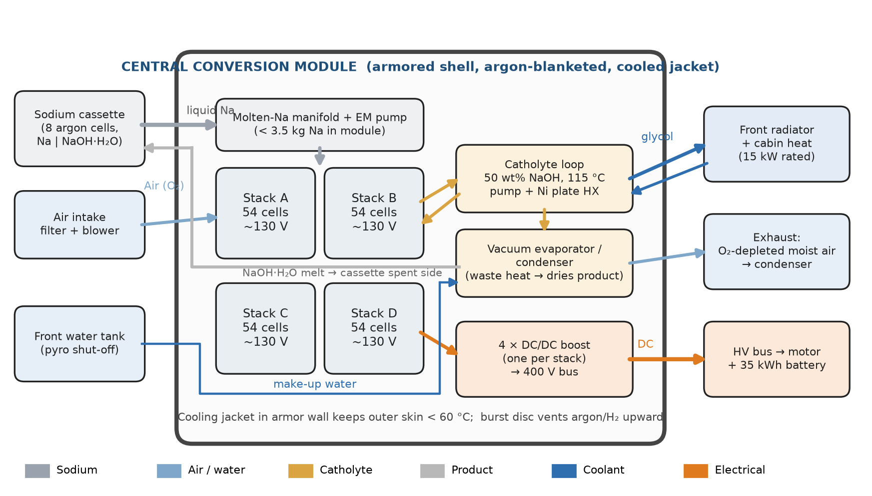
Sodium. An electromagnetic pump with no moving seals meters liquid sodium from the cassette into a heated manifold. Each cell holds only the sodium soaked into its 0.5 mm steel wick. On shutdown the pump reverses and drains the manifold back to the cassette.
Catholyte. About 12 L of 50 wt% NaOH circulates at 115 °C through the cells and a nickel plate heat exchanger. This concentrated solution boils well above the operating temperature, so the loop does not need high pressure.
Product. A bleed stream goes to a vacuum evaporator heated by stack waste heat. It is concentrated to NaOH·H₂O, which stays liquid above about 65 °C, and pumped to the spent side of the cassette. The evaporated water is condensed and reused.
Air. A blower supplies filtered air. Carbon dioxide in the air (about 22 g/h at 30 kW) forms small amounts of sodium carbonate, which leaves with the product bleed instead of building up.
Figure 5. CCM flow schematic.
6. Cooling Design
Cooling has three jobs: remove waste heat from the stacks, keep the armored outer skin cool, and hold the module warm when the car is parked.
Catholyte loop (primary). The catholyte itself carries heat out of every cell, which keeps temperatures even across the stack. It passes through the nickel plate heat exchanger and gives up heat to the evaporator first.
Glycol loop (secondary). A 50/50 glycol loop at 30 L/min takes the remaining heat to a 15 kW front radiator and the cabin heater. The same loop runs through channels in the armor wall, so the outer skin stays below 60 °C even at peak power.
Thermal states. Cold start: a 6 kW heater powered by the battery brings the module to 105 °C in about 20 minutes while the car drives on battery power. Hot standby: vacuum insulation limits heat loss to about 140 W. Long park: catholyte drains to the heated dump tank, because 50 wt% NaOH freezes near 12 °C.
Figure 6. Waste heat at the same electrical output (estimates).
The module derates automatically when the coolant inlet temperature passes 70 °C, for example on a long climb in hot weather. Because peak heat is only about 22 kW, a radiator the size of an EV radiator is enough. Revision 1 needed one the size of a combustion-engine radiator.
7. Armor and Containment
7.1 Wall Layers (Outside In)
Layer
Thickness
Purpose
Ti-6Al-4V skid plate (base only)
5 mm
Road debris, curb and underbody strikes
Ultra-high-strength steel shell
2.5 mm
Main structure; resists intrusion and crushing
Aramid composite spall liner
8 mm
Catches fragments; absorbs impact energy
Glycol coolant jacket
6 mm
Keeps outer skin < 60 °C; absorbs heat in a fire
Vacuum insulation panel
6 mm
Holds the module at operating temperature
316L stainless hermetic liner
1.2 mm
Welded, leak-tight boundary for argon and caustic
Argon gap
4 mm
Inert space monitored for hydrogen and humidity
7.2 Mounting
Four elastomer-isolated mounts carry the module. Each has a frangible bolt designed to shear at about 25 g, so that in a severe crash the armored box separates from the deforming body instead of being crushed by it. Front and rear crush zones contain no energy storage.
7.3 Crash Sequence
Time after impact
Action
0 ms
Crash sensor confirms impact above threshold
< 5 ms
Pyrotechnic high-voltage disconnects open on all four stacks
< 10 ms
Sodium feed valve closes (fail-closed); EM pump stops; pyrotechnic valve shuts the water tank
< 50 ms
Catholyte dump valve opens; catholyte drains by gravity into a sealed nickel tank in the module floor
< 1 s
Argon bottle pressurizes the liner; any hydrogen vents upward through the burst disc
After
Sodium solidifies as it cools; red port gives firefighters access for Class D powder
7.4 Single-Cell Fault
If one membrane cracks, at most about 15 g of sodium can reach catholyte. That releases about 0.65 g of hydrogen and about 0.2 MJ of heat, which the stack and coolant can absorb. Hydrogen sensors in the argon space detect it within seconds. The affected stack is isolated, and the car continues at 75% power.
Total mass is about the same as Revision 1, but this version includes armor and needs about one-eighth of the cooling. The cassette shrinks to about 35 L of sodium plus a 48 L product compartment, compared with 120 L of sodium in Revision 1.
9. Open Risks and Assumptions
Power density. The design assumes 0.30 W/cm². Published hybrid sodium-air cells reach 12.4 mW/cm² with an aqueous catholyte (PMC review, hybrid Na-air batteries) and 34.9 mW/cm² with an acidic catholyte (ACS Applied Materials & Interfaces). Thinner membranes, operation above 100 °C, and better air electrodes would each need to contribute to closing this gap of about 10×.
Membrane life in hot caustic. NASICON can degrade in aqueous media; one study found conductivity falling to about 10⁻⁶ S/cm in solutions with too few dissolved ions (ACS Chemistry of Materials). Long life in 50% NaOH at 115 °C has not been demonstrated.
Ceramic in a car. Thin ceramic plates are brittle. The design relies on compliant cell frames and an isolated module, and it needs vibration and shock qualification.
Product storage next to sodium. NaOH·H₂O contains bound water, so the spent compartment needs a double wall with a monitored argon gap between it and the sodium cells.
Evaporator. Concentrated NaOH has a high boiling point, so the evaporator must run under vacuum to work with heat at 115 °C. It needs detailed design.
10. Story Notes
Drivers hear the CCM rather than see it: a low blower hum at cruise, and a soft tick as the evaporator cycles.
A warm module is a status symbol, because cars parked on hot standby start instantly. Cold cars “wake the stacks” for 20 minutes on battery power.
Losing a stack is a strong scene: a dash warning, a 25% power drop, and a decision whether to push on to the next swap station.
Crash crews look for the red port first. The yellow burst-disc vent pointing at the sky is the visual tell that a vehicle runs on sodium.
Revision 1 figures come from the companion SOV Technical Review below (November 2026). All other numbers are calculated in this study from standard thermochemical data and the stated assumptions. Renderings are artist impressions and are not to scale.
Part II · Revision 1 Technical Review · November 2026
Sodium-Operated Vehicle (SOV)
Energy and mass budget, feasibility redesign, and story-ready version. Technical review of the SOV powertrain module concept.
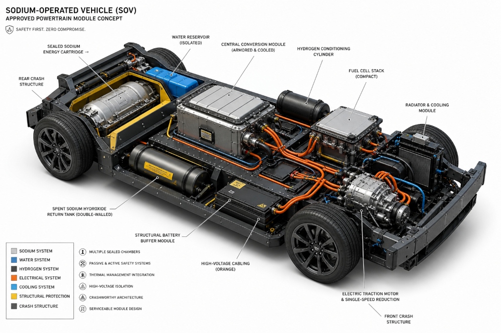
Baseline Chassis Concept Illustration: Sodium-Operated Vehicle (SOV) powertrain module layout reviewed in Revision 1 and superseded in Version 2 by the armored direct sodium-air Central Conversion Module (CCM).
1. Bottom Line
Physics: works. Sodium plus water reliably releases hydrogen, and a fuel cell can turn that hydrogen into electricity. Nothing in the concept breaks conservation laws.
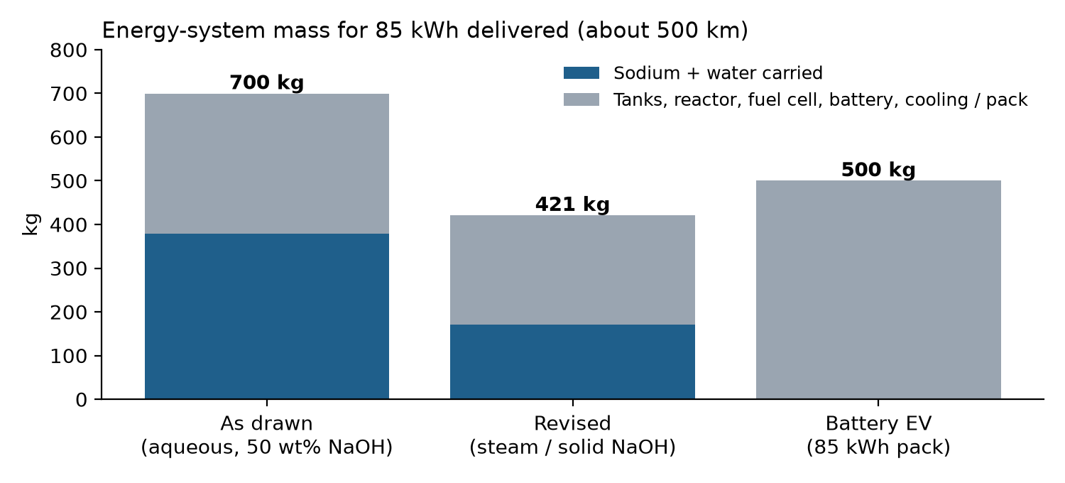
Vehicle packaging: possible, but only after a redesign. The as-drawn aqueous system needs about 700 kg of energy hardware and consumables for an 85 kWh trip, versus about 500 kg for a comparable battery pack. A steam reactor that stores solid hydroxide back in the same cassette cuts this to about 420 kg.
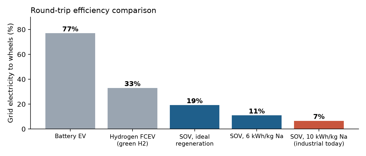
Energy economics: the deal-breaker. Making sodium takes about 10 kWh of electricity per kg, and each kg returns only about 0.66 kWh at the wheels. Round-trip efficiency is about 7% today and at most about 19% even at the thermodynamic limit, compared with about 77% for a battery EV.
Where it makes sense: stockpiled or remote energy (sodium keeps indefinitely when sealed), military and emergency vehicles, or a future with very cheap surplus electricity at coastal sodium plants. That last case also makes a strong science-fiction setting.
2. Assumptions
Reference vehicle: midsize car, 0.17 kWh/km at the DC bus, 500 km range, so 85 kWh delivered.
Fuel cell: PEM, 50% net system efficiency on hydrogen lower heating value (LHV = 120 MJ/kg), sized at 60 kW continuous.
Buffer battery: 10 kWh at about 0.15 kWh/kg pack level, covering peaks up to about 120 kW.
Battery-EV comparison: 85 kWh pack at about 0.17 kWh/kg pack level, so 500 kg.
Standard enthalpies at 25 °C. Hardware masses are engineering estimates, not vendor data.
3. Chemistry and Energy per Kilogram of Sodium
The as-drawn concept uses liquid water and produces dissolved sodium hydroxide:
Making solid or molten hydroxide instead (revised concept) releases less heat, because no heat of dissolution is released:
Na + H₂O → NaOH(s) + ½ H₂, ΔH ≈ −140 kJ/mol
Quantity per 1 kg Na
Value
Moles of sodium
43.5 mol
Hydrogen produced
43.8 g
Hydrogen chemical energy (LHV)
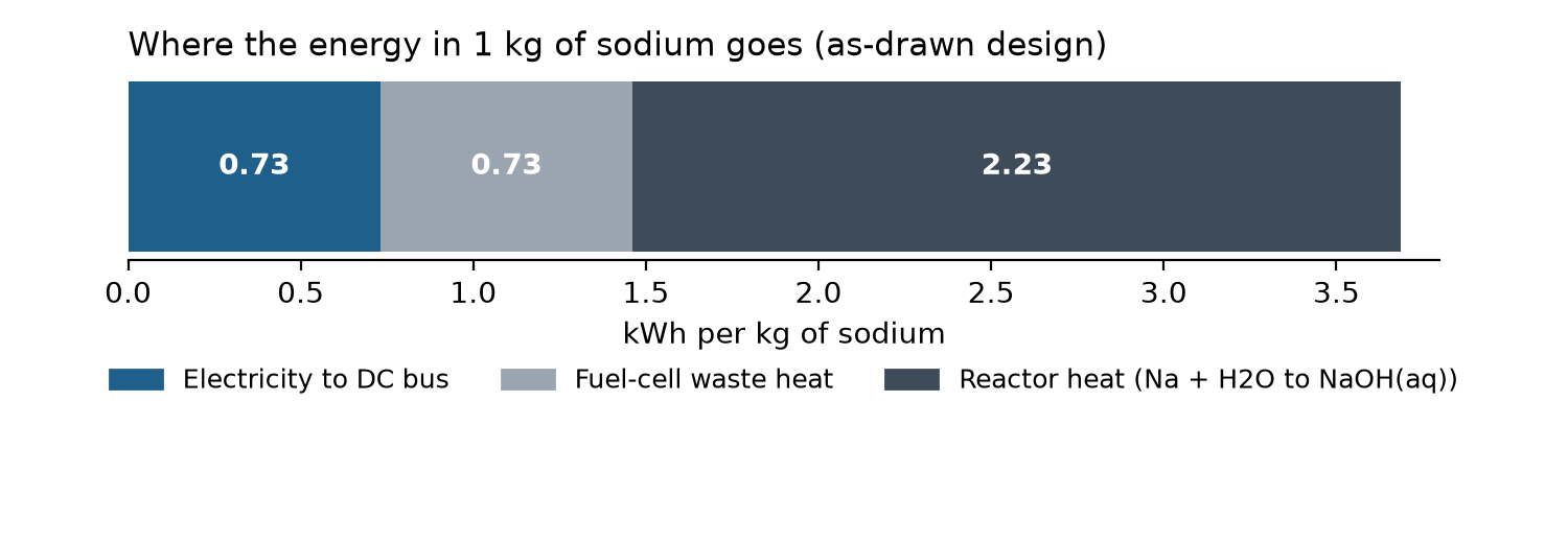
1.46 kWh
Electricity after fuel cell (50%)
0.73 kWh
Fuel-cell waste heat
0.73 kWh
Reactor heat, aqueous product
2.23 kWh
Reactor heat, solid product
1.69 kWh
Water consumed by reaction
0.78 kg
Water returned by fuel cell (theoretical)
0.39 kg
NaOH produced
1.74 kg (0.82 L solid)
Sodium volume
1.03 L
Key point: only about 20% of the chemical energy reaches the DC bus. The reactor releases about three times as much heat as the electricity the system produces. Most of the energy put into making the sodium is lost as heat inside the car.
Figure 1 (Rev. 1). Energy split for 1 kg of sodium in the as-drawn design.
4. Vehicle Mass and Volume Budget
An 85 kWh trip needs 85 / 0.73 ≈ 116 kg of sodium, about 120 L. The sodium mass is about the same in both designs. The difference is everything else carried around it.
4.1 As Drawn: Aqueous System
Sodium hydroxide must stay below about 50 wt% or it crystallizes and blocks lines. That requires carrying extra dilution water equal to the hydroxide mass, about 1.74 kg per kg Na, on top of the 0.78 kg the reaction itself consumes. After recovering 70% of fuel-cell water, the car carries about 262 kg of water at the start and ends the trip with about 405 kg of hot, highly caustic solution.
4.2 Revised: Steam Reactor with Solid Hydroxide
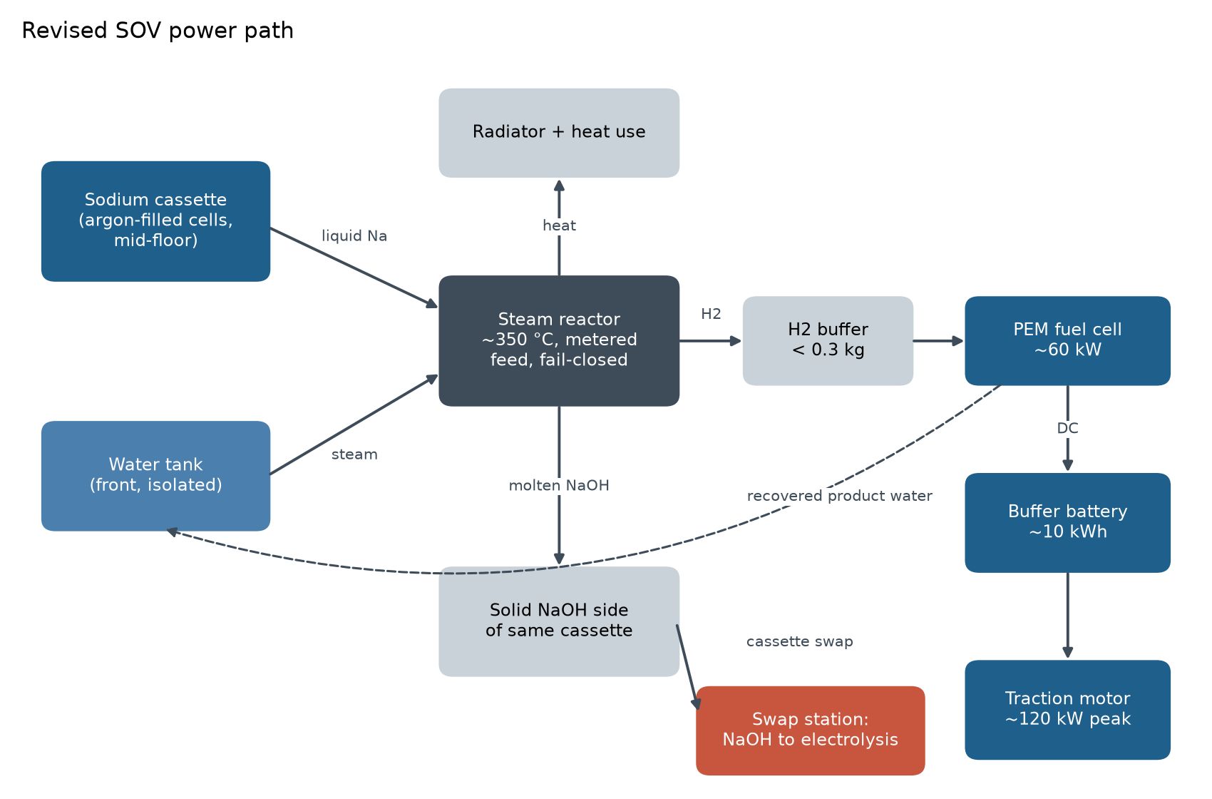
Liquid sodium (it melts at 98 °C) meets metered steam at about 350 °C. The product is molten NaOH (it melts at 318 °C), which drains into the empty side of the same cassette and freezes there. Because 1 kg of sodium (1.03 L) becomes only 0.82 L of solid NaOH, the spent product always fits in the space the sodium vacated. Only reaction water is carried, about 55 kg after 80% fuel-cell water recovery.
Item (kg)
As drawn
Revised
Battery EV
Sodium
116
116
—
Water carried
262
55
—
Tanks / cassette
95
35
—
Reactor and heat exchangers
40
35
—
Fuel-cell system (60 kW)
75
75
—
Hydrogen buffer
15
8
—
Buffer battery (10 kWh)
67
67
—
Extra cooling
30
30
—
Battery pack (85 kWh)
—
—
500
Total
700
421
500
Figure 2 (Rev. 1). Energy-system mass for the same 85 kWh delivered.
Mass change during the trip. In the revised design, the car starts with 171 kg of sodium plus water and returns about 203 kg of NaOH. It gets about 31 kg heavier because the fuel cell pulls oxygen from the air and that oxygen ends up in the stored product. The swap cassette weighs about 150 kg full and about 240 kg spent, so swaps need a robot.
5. Thermal Budget
Operating point
Na use
Reactor heat
Fuel-cell heat
Total
Highway cruise, 25 kW (aqueous)
34 kg/h
76 kW
25 kW
~101 kW
Highway cruise, 25 kW (revised)
34 kg/h
58 kW
25 kW
~83 kW
Fuel cell at 60 kW (revised)
82 kg/h
139 kW
60 kW
~199 kW
A highway cruise rejects about as much heat as a gasoline engine of similar output, so a radiator the size of a combustion-engine radiator is needed, not the small EV-style unit in the drawing. The revised reactor makes high-grade heat at about 350 °C, which can be put to use: keeping the sodium molten, heating the cabin, and, on heavy vehicles, running a small organic Rankine cycle. A 20%-efficient bottoming cycle at cruise would add about 12 kW and raise output to roughly 1.1 kWh per kg Na. That is probably too complex for a car but reasonable for a truck, locomotive, or ship. Sustained full fuel-cell power is heat-limited, so long climbs should draw on the buffer battery and the system should derate.
6. Round-Trip Efficiency
Industrial sodium production by the Downs process uses at least 10 kWh of electricity per kg of sodium (Google Patents, WO2001014616A1), and operating cells run at 7–8 V against a theoretical value of about 4 V (Wikipedia, Downs cell). The thermodynamic floor for recovering sodium from hydroxide (NaOH → Na + ¼ O₂ + ½ H₂O) is about 3.4 kWh per kg Na. With 0.66 kWh reaching the wheels per kg (0.73 kWh × 90% drivetrain):
η(round trip) = 0.66 / E(regen): ≈ 19% at 3.4 kWh/kg, 11% at 6 kWh/kg, 7% at 10 kWh/kg
For comparison, battery EVs reach about 77% and fuel-cell EVs on green hydrogen about 33% on a renewable-electricity basis (Enel Green Power hydrogen factbook, citing T&E). Even under ideal regeneration, the SOV needs about four times the grid electricity of a battery EV per kilometer.
Figure 3 (Rev. 1). Grid electricity to wheels. SOV values calculated in this report; BEV and FCEV values from the T&E figures above.
7. Revised Concept for Real-World Feasibility
7.1 Design Changes
Move the sodium. Put the sodium cassette low in the mid-floor tunnel between the axles, inside the side-impact rails. Never place it in a crush zone.
Separate sodium and water. Move the water tank to the front, away from the sodium. Feed water to the reactor only through a single metered steam line with a fail-closed valve. No bulk water should ever be able to reach the sodium.
Subdivide and inert. Split the cassette into about eight sealed 15 kg cells under argon, so a breach exposes only a small fraction of the sodium.
Make the reactor small. Keep sodium solid in storage and melt only what is about to be pumped, using electromagnetic pumps like those in sodium-cooled reactors. Keep reacting inventory under about 1 kg.
Store solid product. Freeze the molten NaOH into the vacated half of the cassette. This removes the 262 kg dilution-water penalty and the caustic-liquid tank.
Keep hydrogen inventory tiny. Use a low-pressure buffer under 0.3 kg instead of a large cylinder, and condense moisture before the fuel cell.
Size cooling like a combustion car. Plan for about 85 kW continuous heat rejection, use reactor heat for cabin and cassette heating, and derate at high ambient temperature.
Crash logic. On impact: pyrotechnic water shut-off, reactor dump to a dry catch volume, hydrogen vent upward, and high-voltage disconnect. Sodium at ambient temperature is solid and fairly inert when no water is present.
Relabel. Change “Approved Powertrain Module” to “Concept” or “Proposed” unless it is fictional branding.
Figure 4 (Rev. 1). Revised SOV power path.
7.2 Best-Fit Applications
Long-duration stored power: sodium stores indefinitely in sealed cassettes with no self-discharge, unlike batteries or compressed hydrogen.
Military, remote-mine, polar, and disaster-response vehicles where logistics matter more than efficiency.
Heavy vehicles and ships that can use the high-grade reactor heat with a bottoming cycle.
Places with stranded or curtailed electricity that would otherwise go unused, so low round-trip efficiency costs little.
7.3 Open Engineering Risks
Side reactions above about 400 °C (Na + NaOH forming Na₂O and NaH) that reduce hydrogen yield.
Caustic corrosion of reactor alloys at 350 °C; nickel alloys are the usual answer.
Freeze/thaw cycling of sodium and hydroxide on cold starts; needs electric preheat from the buffer battery.
Regeneration energy and plant cost: the efficiency barrier is at the sodium plant, not in the vehicle.
Regulation: shipping and storing sodium is restricted as a water-reactive hazardous material, so the cassette would need its own certified packaging.
8. Story Version: Technical Plausibility Upgrades
If the SOV is for fiction, the goal is a world where the efficiency problem has already been solved somewhere else, so the vehicle itself only needs to be internally consistent.
8.1 Make the World Pay the Energy Bill
Set it in a sodium economy. Coastal “salt foundries” run on cheap fusion, orbital solar, or surplus tidal power. Electricity is nearly free at the coast, but grids inland are weak or broken. Sodium becomes the way to ship coastal energy inland, so its 7–19% efficiency is an accepted tax.
Spent cassettes are valuable. Drivers get a deposit back for returning a NaOH cassette, which creates a scavenger economy, cassette theft, and counterfeit cells.
Swap, not refuel: a robotic bay pulls the 240 kg spent cassette and drops in a fresh 150 kg one in under two minutes.
8.2 Sensory and Procedural Details
After shutdown, the car ticks and hisses for minutes as the reactor purges hydrogen and the sodium line drains back.
Cold starts take 30–90 seconds while the battery melts the feed sodium; drivers call it “thawing the salt.”
Under hard climbs the cooling fans roar like an old combustion car, and the dash shows reactor temperature next to charge level.
Maintenance crews wear face shields and nitrile; a hydroxide burn is a slow, painful injury, which is useful for tension.
Firefighters carry Class D powder and never use water on an SOV crash. That is a strong scene hook.
8.3 Failure Modes Worth Writing
Water ingress after a flood or river crossing: the cassette seals hold, but one breached cell fizzes, cracks, and burns orange.
Contaminated water feed: sabotage with salt water or antifreeze fouls the reactor and the car limps on battery.
Hydroxide freeze-up in arctic conditions: the product line plugs and the car must stop to keep it from cracking.
Overheat on a long grade: the system derates, and the character has to choose between speed and the reactor.
Electric traction motor and single-speed reduction
Crash-dump catch volume and upward hydrogen vent
8.5 Illustration Specification Prompt
Photorealistic technical cutaway of a midsize electric car chassis on a white background, three-quarter top view, labeled callouts in clean sans-serif. A long armored sodium cassette with eight sealed cells runs down the center floor tunnel between the axles, split into a silver sodium side and a white solid-hydroxide side. A compact dark steam reactor block sits just ahead of it, with a thin blue steam line from a small blue water tank in the front. A small hydrogen buffer, a compact fuel-cell stack, and a thin structural buffer battery sit beside it, with orange high-voltage cables. A large front radiator, a front electric motor, and clearly marked front and rear crush zones with no energy storage in them. Legend: sodium, water, hydrogen, electrical, cooling, structure. Title: “SODIUM-OPERATED VEHICLE (SOV) — Cassette Powertrain Concept”.